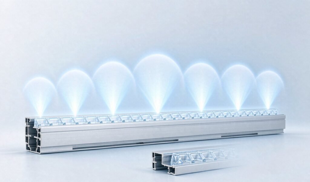
Most people specify a linear lens the way they specify a lamp: choose the lumen package first and trust the optics to sort themselves out. They rarely do. Beam angle decides whether a corridor reads as one continuous wash of light or as a row of bright pools with dark gaps between them.
This guide covers the seven beam angles available in extruded linear lenses (35°, 45°, 60°, 85°, 95°, 100° and 105°) and how to match one to a mounting height and a fixture spacing before you commit to tooling.
What beam angle actually measures
Beam angle is the width of the cone of light, measured where the luminous intensity has fallen to half its peak value. In photometry that point is called full width at half maximum, or FWHM. It belongs to the optic rather than to the LED or the driver.
Two consequences follow from that definition:
- A narrower beam concentrates the same lumens into a smaller area, raising peak intensity and throwing light farther.
- A wider beam spreads the same lumens thinner, lowering glare and helping to blend the output of adjacent LEDs.
The total output stays the same when you change beam angle, and only the distribution moves. Two fixtures with identical lumen packages can therefore look completely different in the same room, which is why “more lumens” is usually the wrong answer to a uniformity complaint.
The seven angles and what each is normally used for
Extruded linear lenses are produced across a spread of about 35° to 105°. In practice each band maps to a recognisable job:
| Beam angle | Typical use | Why it works there |
|---|---|---|
| 35° | Reveals, cove accents, grazing walls, display shelves | Tightest pool and highest intensity at distance; keeps light off surrounding surfaces |
| 45° | Task lighting, under-shelf, workbench, retail shelving | Still focused, but enough spread to cover a working surface evenly |
| 60° | Aisles, corridors, medium-height general lighting | The usual compromise: reaches the floor without dark bands between fixtures |
| 85° | Offices, classrooms, retail ambient at 2.7 to 3 m ceiling height | Wide enough to overlap neighbours; keeps contrast comfortable |
| 95° | General commercial areas, open-plan spaces | Softer edges, less visible scalloping where light lands on walls |
| 100° | Low ceilings, backlit panels, wall-washing | Very even; hides LED pitch when the optic sits close to the LED array |
| 105° | Wide-area ambient, coves, indirect fixtures | Broadest blend, chosen where uniformity matters more than throw |
The full angle range we extrude sits in the lens catalogue: see linear LED lenses and optical LED lenses.
The two numbers that decide it
Beam angle is never chosen in isolation. Two site measurements fix it: mounting height, the distance from the lens to the task surface, and fixture spacing, the centre-to-centre distance between adjacent luminaires.
The useful figure is spacing divided by mounting height. As a working rule for continuous runs, a ratio between roughly 1.0 and 1.2 paired with a 60° to 85° optic gives acceptable uniformity in most commercial interiors. Push the ratio much beyond that and scalloping appears no matter how many lumens you add.
High-bay work combines a large mounting height with a spacing usually fixed by the building grid, so narrower beams tend to suit it, because the light has farther to travel. See industrial lighting applications. Desks and teaching spaces pull the other way: the ceiling is low and people often look sideways at the fitting, so the wide end of the range stops the lens from becoming a bright stripe in the field of view. See office lighting. Continuous architectural runs are judged almost entirely on how unbroken they look, which pushes them toward 100° or wider. See linear lighting.
Where people get it wrong
Three mistakes account for most disappointing installations:
- Specifying by lumens only. Two identical fixtures fitted with 60° and 100° optics produce very different results on the same grid.
- Ignoring LED pitch. A narrow beam over a widely spaced LED array produces visible hotspots, and the closer the LEDs sit together, the narrower you can go before individual points appear. The mechanism is covered in more detail in how LED diffusers improve light distribution.
- Changing the optic after tooling. On an extruded linear lens the optical structure is part of the profile or ground into the die, so adjusting the angle later usually means new tooling rather than a new part number.
When a lens is not enough on its own
A lens shapes light; a diffuser softens it. Many fixtures need both, the lens to put light where it belongs and a diffuser or frosted surface to erase LED pitch. The two decisions interact, because a diffuser placed directly against a wide-beam optic often undoes the distribution the lens was chosen to create. If you are still deciding between finishes, clear vs frosted LED diffuser covers the trade-off properly.
Checklist before you send the drawing
- Mounting height and fixture spacing confirmed on site, not assumed
- Target beam angle chosen against the table above
- LED pitch and array width recorded
- Decision made on lens alone versus lens plus diffuser
- Acceptance criterion agreed in writing, a uniformity ratio rather than a single lux figure
Frequently asked questions
Can the beam angle be changed later?
Usually this means new tooling, because the optical structure is part of the extrusion die or the profile itself rather than a separate part you can swap out.
Does a wider beam cost me light?
No. Total output stays the same and is redistributed. Apparent brightness at any single point drops, but coverage improves and hotspots reduce.
Which angle hides LED hotspots best?
100° to 105°, combined with adequate diffusion. Narrow beams make the position of each individual LED far easier to see.
If you have the mounting height and spacing figures, we can usually tell you which of the seven angles will work and quote the profile. Send the drawing and get a quote.