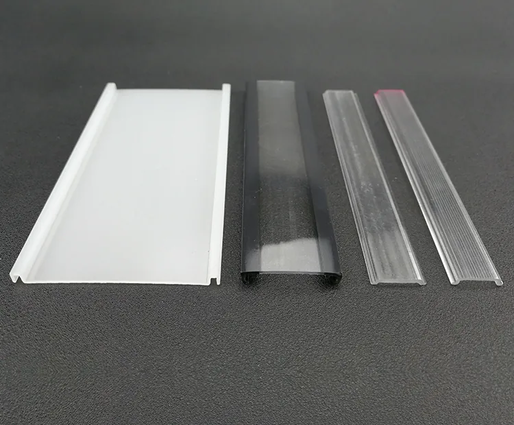
A linear lens and a linear diffuser clip into the same aluminium channel, both ship in 2 m or 3 m lengths, and both get called a cover on the drawing. Run them in a photometric test and they behave like opposite parts. One decides where the light goes. The other decides how evenly it leaves the face.
The arguments usually start the same way. A buyer orders the part that looked right in a sample bag, fits it, then reads the report and finds a bright stripe down the aisle, or a beam that floods 120 degrees when the layout asked for 60. The part was not defective. It was answering a different question.
The difference in one sentence
A linear lens bends light. A linear diffuser scatters it.
Inside a lens profile the light hits angled surfaces, either prism ribs on the exit face or total internal reflection steps on the sides, and leaves in a direction set by the geometry. The output has an edge: walk under a 45 degree lens line and you can see where the light stops, which is why lens profiles carry accent, wall wash and high ceiling work. Clear grades keep most of the flux, but the emitter stays visible. Any mismatch between LED pitch and lens pitch turns into bright spots on the floor.
A diffuser does the reverse. Scatterers sit in the resin, or the surface is textured, and each point of light is spread before it reaches the room. There is no beam to speak of, only a distribution curve that falls off gradually. The LED image disappears, which is what you want above a desk, and the cost is flux lost to back scatter.
Linear lens vs linear diffuser: the comparison table
| Property | Linear lens | Linear diffuser |
|---|---|---|
| Job in the fixture | Directs light into a defined beam | Spreads light evenly across the face |
| Beam angles available | 35, 45, 60, 85, 95, 100, 105 degrees | No beam angle; quoted as a distribution |
| LED image | Visible unless pitch is matched | Hidden from normal viewing angles |
| Transmission | High on clear grades, thin sections | Lower, set by grade, thickness and scatter load |
| Surface | Prism ribs, lenticular rows, TIR steps | Matte, frosted, opal or fine texture |
| Material choice | PMMA for clarity, PC where impact is a risk | PMMA for UV stability, PC for heat and impact |
| Typical housing | Track, pendant, high bay, wall wash channel | Office lines, troffers, shelving, cove |
| Failure when mismatched | Hot spots, scallops on the floor, glare at eye height | Flat but dim face, poor utilisation, UGR that will not drop |
Reading the beam number before you compare prices
A lens datasheet quotes a beam angle measured where intensity falls to half of peak, in one plane. Two traps sit in it. The first is the plane: a lens reading 60 degrees in C0 to C180 can read 40 degrees in C90 to C270, and a linear part is elliptical by nature. The second is where it was measured. Numbers taken 100 mm from the face and numbers taken at 1 m rarely agree.
Ask for an IES file instead of a single figure. Open it, check both planes, and confirm the beam holds along the length of the fixture, not just across it. A diffuser needs different numbers: uniformity across the face, the ratio between light straight down and light at 60 degrees off axis, and, over a desk, the UGR value. A diffuser that quotes “120 degree beam” is quoting nothing you can design against.
Where the application sets the target, the choice is mostly mechanical. A 6 m mounting height over a 3 m aisle needs the 35 or 45 degree options to keep light on the shelf and off the racking above it. A 2.8 m office ceiling wants 95 to 105 degrees, or a diffuser, because anything narrower leaves dark bands between rows. The LED lens beam angle guide covers the full set with mounting heights attached.
Three checks that settle the choice
- Pitch against pitch. Measure LED pitch on the strip, then rib pitch on the lens. If 25 mm LEDs meet a 12.5 mm rib pattern the lens maps cleanly; if the two do not divide, expect a scalloped floor. With a diffuser the test is scatter strength: at 30 mm pitch a 1.5 mm opal wall shows dots, a 3 mm grade does not.
- Clearance between emitter and part. A narrow lens needs air to work. Below roughly 8 mm of gap the beam has not formed when light leaves the prism, and a 35 degree lens behaves like a 70 degree one. Diffusers need a mixing distance, usually 6 mm to 10 mm, or the face goes bright directly over each LED.
- The number in the lighting design. If the design specifies UGR below 19, glare control or a cutoff angle, an opal diffuser alone will not get there and you need a lens, or a lens under a diffuser. If it specifies uniformity over a task plane, the diffuser does the work and a lens fights it.
Running both in the same fixture
Office lines above a certain quality threshold use a stack: a linear lens close to the LEDs, and a diffusing cover at the housing face. The lens takes the peak out of the downward direction and pushes light sideways, the diffuser removes the last of the LED image. The price is a second part, extra height in the section, and roughly 8% to 15% of the flux.
Two things decide whether the stack works. The gap between lens and diffuser has to be wide enough for the redirected light to spread, and the lens cannot be so narrow that the diffuser is asked to re-spread a beam it was never designed for.
For single part builds, the linear LED lens range covers the profiles used with 35 to 105 degree optics, and the extruded linear diffuser profile range covers the opal and frosted covers that drop into the same channels. If the brief is still open, the explainer on what a linear LED diffuser is sets out how the grades differ before you pick a thickness.
What to put on the drawing
Either part is only as good as the section it is cut from. A drawing that carries the section with dimensions, resin grade, wall thickness at the diffusing face, transmission target, surface finish and cut length tolerance will price and run without a second round of questions. Add the LED pitch and the mounting height, and the optics get checked before the die is cut, not after the first sample.
Production sits on 20+ extrusion lines, with daily output above 10,000 pieces on running parts. Minimum order is 500 pieces per section. Quality is audited to ISO 9001:2015 under CQC certificate 00124Q34175R1S/3300, valid to 2027-05-16. The UL recognitions are material level Component Plastics yellow cards E242424 and E300275, which cover the resin, not an assembled luminaire, so the fixture still has to meet the requirements of the market it ships to. Flammability, RoHS and electrical performance must comply with the standards your destination market asks for.
Widths on prismatic covers run from 23 mm to 195 mm, profile weights from 10 g/m to 2000 g/m, and transmission from 0% to 97% depending on grade and section. The linear lighting diffuser page collects the fixture types these sections were drawn for. When the section is ready, request a quote for a linear lens with the drawing attached, and say whether the fixture also needs a diffusing cover.
Frequently asked questions
Can I use a linear lens with no diffuser at all?
Yes, and plenty of accent and high bay fixtures do. The conditions are a matched LED pitch, clearance for the beam to form, and a spec that tolerates seeing the emitter from below. At office mounting heights the raw LED image is usually why a sample gets rejected.
Does a diffuser cut output by its transmission figure?
Roughly, but not exactly. Some light reflects into the housing and gets recycled, some is absorbed in the scatter layer. A 70% grade in a white cavity often delivers more than 70% of bare LED flux, and less in a black housing. Measure the fixture, not the sheet.
Which part brings UGR down further?
The lens, in almost every case. Glare comes from high intensity at shallow angles, and only the lens moves intensity out of that zone by design. A diffuser lowers the peak but sends light sideways, so low UGR usually needs the stack.
Can I swap a diffuser for a lens in a housing I already own?
Only if the section height allows it. The lens needs clearance below the board and its snaps have to land on the same rails. If both fit it is a straight swap; if the housing was drawn around a flat cover, a new section is cheaper.